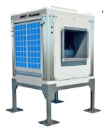
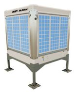
Having selected the size of evaporative coolers to provide the most suitable amount of air changes to your building to effectively cool it, the next stage is to sort out he cool air distribution and choose the best means of distributing the cooled air to the internal space. Generally the internal cool air distribution arrangements and the external space availability and access will steer the choice of outlet to the coolers, i.e. if the ducting is to be fitted to the top, base or side.
The choice of air distribution system that will attach to the evaporative cooler will depend on the layout of the space inside and where and how the occupants of the building operate. The tables and diagrams below give quite simplified performance details on the different options which are in most cases specific to particular models of cooler.
Cool Air Distribution Using Nozzle Diffusers

Cool air distribution using nozzle diffusers
| Flow | m3/h | 50 | 100 | 250 | 500 | 750 | 1000 | 1250 | 1500 | 1750 |
| Pressure drop | Pa | 0.3 | 1 | 6 | 23 | 50.8 | 90.3 | 140.8 | 202.5 | 275.5 |
| Discharge velocity | m/s | 0.6 | 1.2 | 3 | 6.1 | 9.1 | 12.2 | 15.2 | 18.3 | 21.3 |
| D | m | 1 | 1.9 | 4.8 | 9.5 | 14.3 | 19.3 | 24.5 | 29.8 | 35.2 |
| L | m | 0.7 | 1.3 | 3.4 | 6.7 | 10.1 | 13.7 | 17.3 | 21 | 24.9 |
| H | m | 0.7 | 1.3 | 3.4 | 6.7 | 10.1 | 13.7 | 17.3 | 21 | 24.9 |
| W | m | 0.5 | 0.8 | 1.8 | 3.5 | 5.2 | 7 | 8.8 | 10.6 | 12.5 |
Note: Range is given assuming a residual velocity of 0.5 m/s. Values are estimated, obtained through use of cf design program simulation and theoretical calculations.
Cool Air Distribution Using 3 Way Diffuser
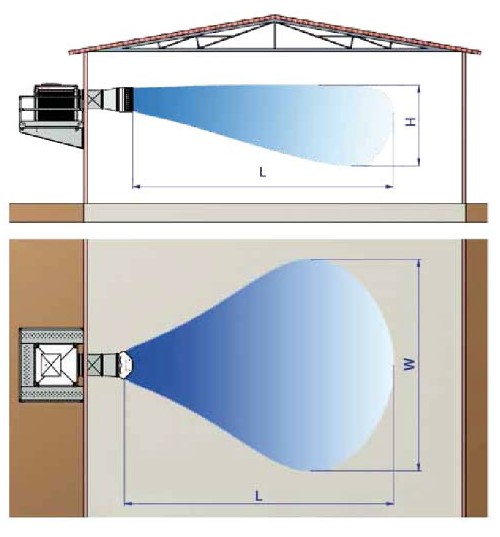 Cool Air Distribution Using 3 Way Diffuser | 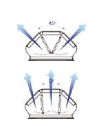 3 Way Diffuser settings |
| Diffuser model | DCH 3/10 | DCH 3/10 | DCH 3/10 | DCH 3/10 | DCH 3/10 | DCH 3/30 | DCH 3/30 | DCH 3/30 | DCH 3/55 | |
| Evaporative cooler size | AD-07 | AD-09 | AD-12 | AD-15 | AD-30 | AD-35 | AD-40 | AD-55 | AD-70 | |
| Flow | m3/h | 5500 | 9000 | 12000 | 15000 | 28000 | 32000 | 38000 | 54000 | 63000 |
| Diffuser angle setting | 0º | 0º | 0º | 0º | 0º | 0º | 0º | 0º | 0º | |
| Pressure drop | Pa | 5 | 11 | 18 | 29 | 18 | 25 | 35 | 108 | 162 |
| Discharge velocity | m/s | 3.8 | 6.2 | 8.3 | 10.4 | 9 | 10.3 | 12.3 | 15.2 | 17.7 |
| L | m | 12 | 19.7 | 26.3 | 32.8 | 43.8 | 50.1 | 60.3 | 69 | 81.5 |
| H | m | 3.6 | 5.5 | 7.1 | 8.7 | 11.6 | 13.2 | 15.7 | 17.9 | 21 |
| W | m | 5.7 | 9 | 11.8 | 14.6 | 19.5 | 22.1 | 26.5 | 30.2 | 35.5 |
| Diffuser angle setting | 45º | 45º | 45º | 45º | 45º | 45º | 45º | 45º | 45º | |
| Pressure drop | Pa | 21 | 48 | 85 | 133 | 93 | 125 | 184 | 192 | 287 |
| Discharge velocity | m/s | 4.7 | 7.6 | 10.2 | 12.7 | 10.9 | 12.4 | 14.7 | 18.2 | 21.2 |
| L | m | 9.9 | 16.2 | 21.6 | 27 | 35.4 | 41 | 49.3 | 59.5 | 70.3 |
| H | m | 3 | 4.6 | 5.9 | 7.3 | 9.5 | 10.9 | 13 | 15.6 | 18.3 |
| W | m | 8.8 | 14 | 18.5 | 22.9 | 30.2 | 34.8 | 41.7 | 50.2 | 59.1 |
Note: range is given assuming a residual velocity of 0.5 m/s, with the slats on the grill in a horizontal position and the deflectors at 0º and 45º. Values are estimated, obtained through use of cf design program simulation and theoretical calculations.
Cool Air Distribution Using 6 Way Diffuser
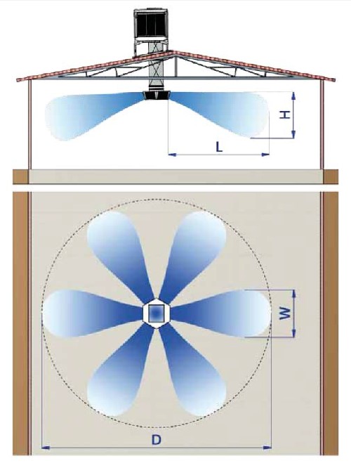
Cool Air Distribution Using 6 Way Diffuser
| Diffuser model | DCH 3/10 | DCH 3/10 | DCH 3/10 | DCH 3/10 | DCH 3/10 | DCH 3/30 | DCH 3/30 | DCH 3/30 | DCH 3/55 | |
| Evaporative cooler size | AD-07 | AD-09 | AD-12 | AD-15 | AD-30 | AD-35 | AD-40 | AD-55 | AD-70 | |
| Flow | m3/h | 5500 | 9000 | 12000 | 15000 | 28000 | 32000 | 38000 | 54000 | 63000 |
| Pressure drop | Pa | 25 | 60 | 107 | 168 | 106 | 138 | 194 | 232 | 318 |
| Discharge velocity | m/s | 4.9 | 8.1 | 10.7 | 13.4 | 11 | 12.6 | 15 | 15.1 | 17.6 |
| L | m | 7 | 11.4 | 15.2 | 19.2 | 23.6 | 27.3 | 32.9 | 40.4 | 47.7 |
| H | m | 2.6 | 4.1 | 5.4 | 6.8 | 8.3 | 9.6 | 11.5 | 14.1 | 16.6 |
| W | m | 3.3 | 5.2 | 6.8 | 8.5 | 10.6 | 12.1 | 14.5 | 17.8 | 21 |
| D | m | 14.9 | 23.8 | 31.4 | 39.5 | 48.7 | 56.1 | 67.2 | 82.6 | 97.3 |
Note: range is given assuming a residual velocity of 0.5 m/s, with the slats on the grill in a horizontal position and the deflectors at 0º and 45º. Values are estimated, obtained through use of cf design program simulation and theoretical calculations.
There is no reason why, say, 2 or 3 diffusers cannot be fitted to a single evaporative cooler, it just means that the airflow splits 2 or 3 ways and the air throw and spread form each diffuser is reduced, although in doing this it is worth noting that any increase in pressure resistance due to ducting is offset by the reduced pressure resistance due to the diffusers resulting from the lowered grill velocity, and that the total pressure drop is within the capability of the evaporative coolers fan.
In most cases distribution ducting can be arranged within the capability of the standard fan, however as these evaporative coolers are built to order there is always the option of fitting it with a higher pressure fan if required, but for this to happen we need to be involved in the design stage of the project.

